Diesel engines Pv actual processes thermodynamics cycles nuclear thermodynamic four 4 the diesel engine cycle
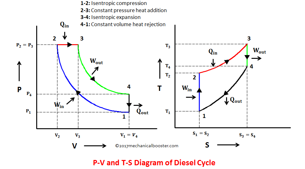
Diesel Cycle – Process with P-V and T-S Diagram - Mechanical Booster
Timing stroke engine diagram diesel cycle two figure Diesel engine diagram pv cycle air standard compression ratio theoretical gif typical Engine petrol stroke engines combustion computerized mpfi extrudesign ignition ic fig4
4 stroke engine diagram
Diagram engine stroke diesel cycle explanation simple actual fourEngine carnot combustion process constant thermodynamic duckduckgo Diesel cycle – process with p-v and t-s diagramMechanical engineering thermodynamics.
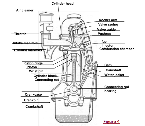
The basics of the compression ignition engineStroke combustion internal supplementary intake tdc explanation piston fourstroke forces valves compression bdc crankshaft plug enters Diesel engine diagram mechanical engineering car piston parts cylinder engg motors engines motor jack head resetsg system members figure chooseDiesel engine cycle.

Pv combustion four mesin dieselmotor diagramm siklus bakar motore diagramma interna combustione proses derivation explanation
Diesel cycle: process, pv diagram, efficiency with derivationFour-stroke combustion engine and supplementary explanation diagram The diesel engineMechanical technology: sketch p-v diagram of petrol engine & diesel engine.
Engine diesel stroke compression ignition engines four principle gasoline principles cycle working exhaust disadvantages spark beginners intake power difference highDiesel engine diesel cycle internal combustion engine pressure volume Diesel cycle thermodynamics engineering ideal mechanical ptEngine diesel diagram petrol cycle sketch pv.

Diesel engine stroke cycle operation combustion internal engines working fuel gasoline basic four strokes when piston car ic two air
Diesel cycle: definition, process, pv and ts diagram, derivationActual and ideal diesel cycle The working and maintenance of a diesel engine,Figure 3-7.timing diagram of a two-stroke-cycle diesel engine..
Diesel cycle diagram process processes four working mechanical boosterDiesel cycle diagram pv ts efficiency process pdf definition derivation application notes Pressure diagram engine combustion internal volume diesel cycle car save.

Diesel Cycle – Process with P-V and T-S Diagram - Mechanical Booster

The Diesel Engine

Actual and Ideal Diesel Cycle | Comparison | nuclear-power.com

Diesel Cycle: Definition, Process, PV and TS Diagram, Derivation

Mechanical Engineering Thermodynamics - Lec 16, pt 3 of 6: Ideal Diesel
Diesel Engines | The function of Car Engine and Cooling System.

Diesel Cycle: Process, PV Diagram, Efficiency with Derivation

4 Stroke Engine Diagram

THE BASICS OF THE COMPRESSION IGNITION ENGINE